Rainbow Clock
July 2023
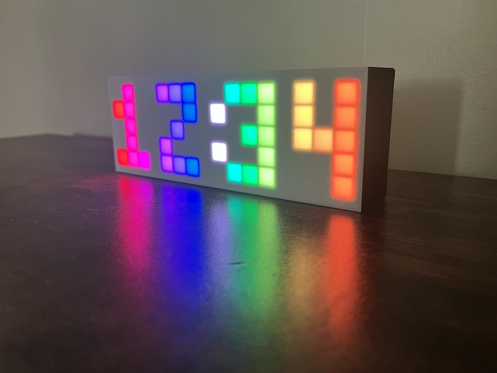
The Rainbow Clock is simply a digital clock with rainbow digits, but it’s also more than that. It is a tool for learning how to program LEDs. There’s a QR code on the back that takes you to a guide that walks you through setting up your computer to upload code to the Rainbow Clock, and then coding your own LED patterns to display on the clock’s grid of LEDs.
Materials
- Black PLA filament for the main container box
- White PLA filament for the screen
- ESP32
- 16x16 LED matrix cut into three 5x16 sub-grids
- Square rocker switch
- 2-pin momentary button
- Data-sync 3ft micro USB cable
Process
- Hingebox design
- Latch design
- ESP32 mount design
- Slice & 3D Print
- Screens
- LED grids
- Accommodating different start pixels in code
- Wiring
- Learn to program LEDs guide
- Code
Hingebox design
I started with this 3D model from Thingiverse: Hinge box with premounted lid.
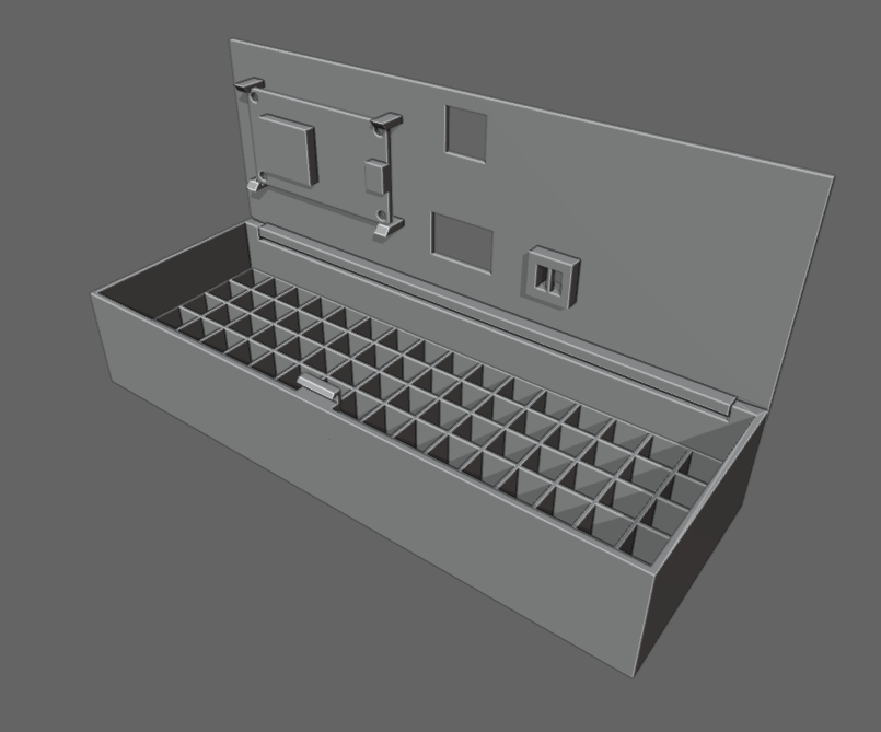
I made the following changes to the Thingiverse hinge box model:
- Removed the bevel to give the box sharp edges.
- Resize to 167mm x 60mm
- Replaced the latch with my own latch design.
- Replaced bottom of box with grid of square holes for LEDs to shine through.
- Added mounts to the lid for the ESP32, button, and switch.
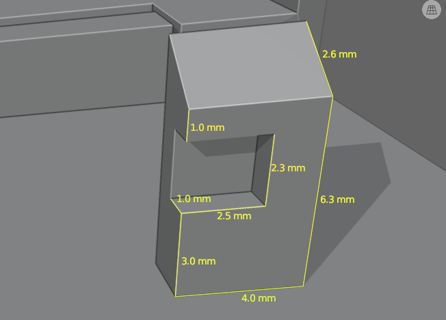
Latch design
I went through several iterations of latch designs! The first one didn’t even close, the second one closed but kept popping open, and the third was great but I tweaked the measurements 3 times before I was satisfied.
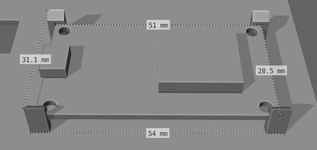
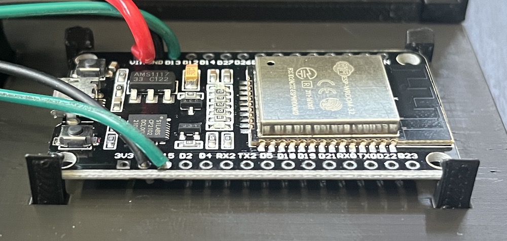
ESP32 mount design
This was the first time I’d tried this method of mounting boards. Previously I was mounting boards with little screws through the holes in the corners, or just glueing them down. But I’m very excited about how this mount design turned out. To snap the board in, I nestle the bottom two corners into the tab slots and then snap in the top two corners. And to release, I bend the top two tabs away and pull up on the board.
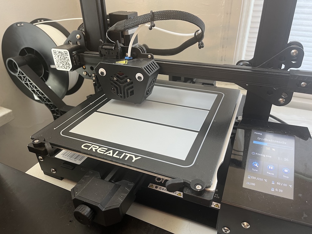
Slice & 3D Print
You can find all the STL files here.
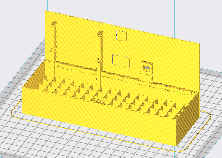
- Infill density: 0
- Support Z Distance: 0.4
- Hingebox.stl:
(0, 0, 0) - Hingebox-grid.stl:
(0, 0.7, 0) - I also added a support block to the button mount at
(27, -28, 42)
Screens
The front screen of the clock is 3d printed separately in white PLA and then glued onto the hingebox. The dimensions are the same as the hingebox (167mm x 60mm), and 0.8mm thick, which ends up being 4 layers of 3d printed filament.
LED grids
I started with a 16x16 pixel matrix and cut it into three 5x16 pixel sub-grids.
I didn’t have a wiring schematic for the grid, so I mostly guessed where to cut. Since there are 16 rows of LEDs and only 15 rows of capacitors, I tried to keep 5 rows of each per subgrid, leaving the remaining row capacitor-less, but I don’t know how the capacitors are wired to the pixels or if their placement is related at all to the data connection between each LED. The LEDs in the remaining row still work individually but the data line along that row was lost.
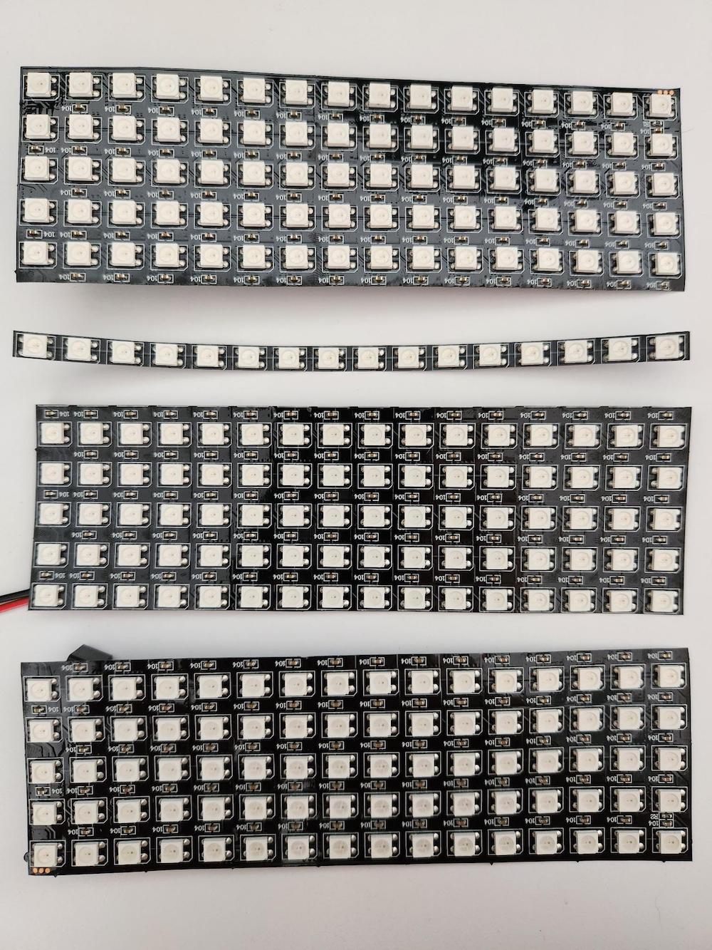
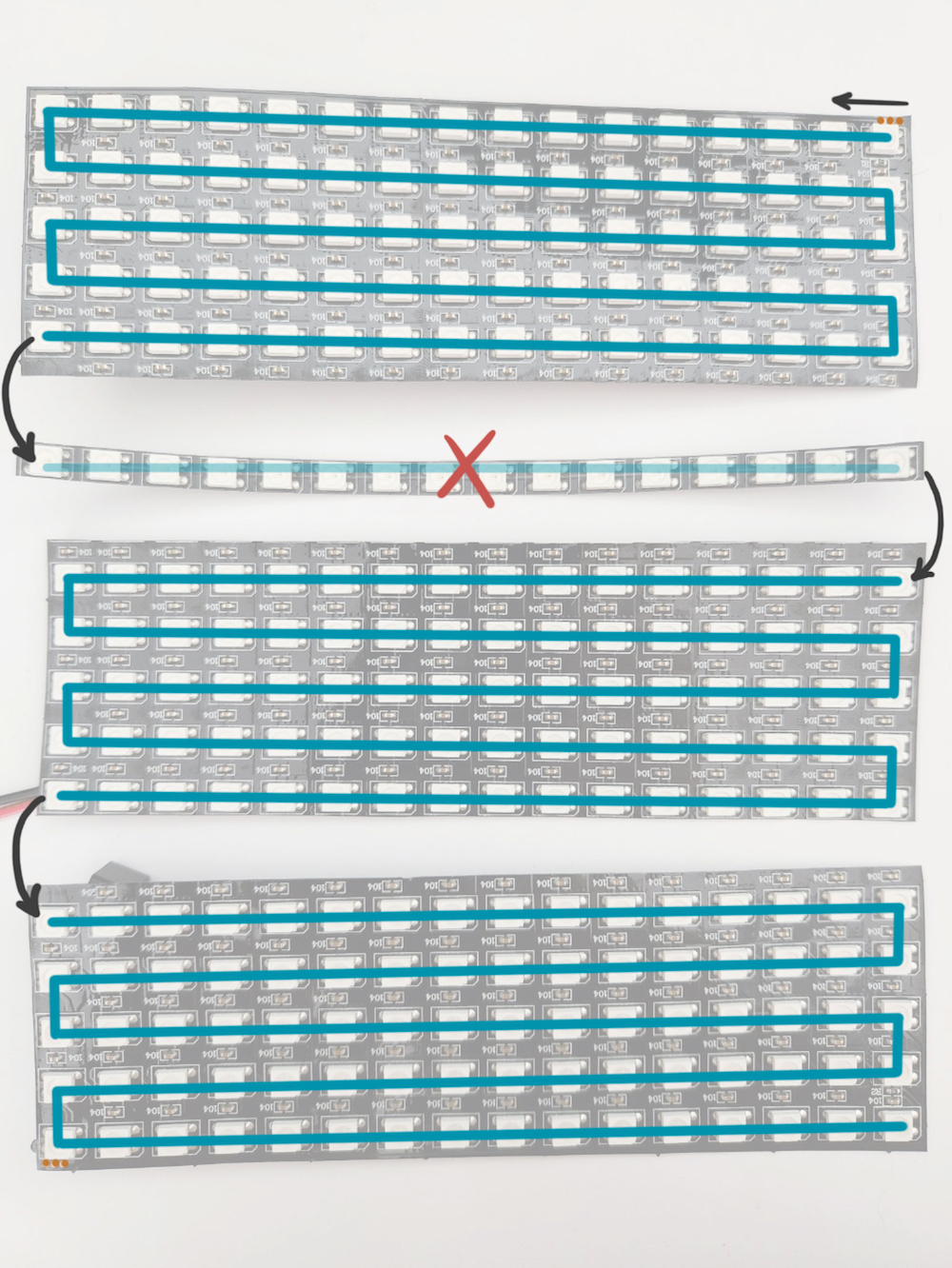
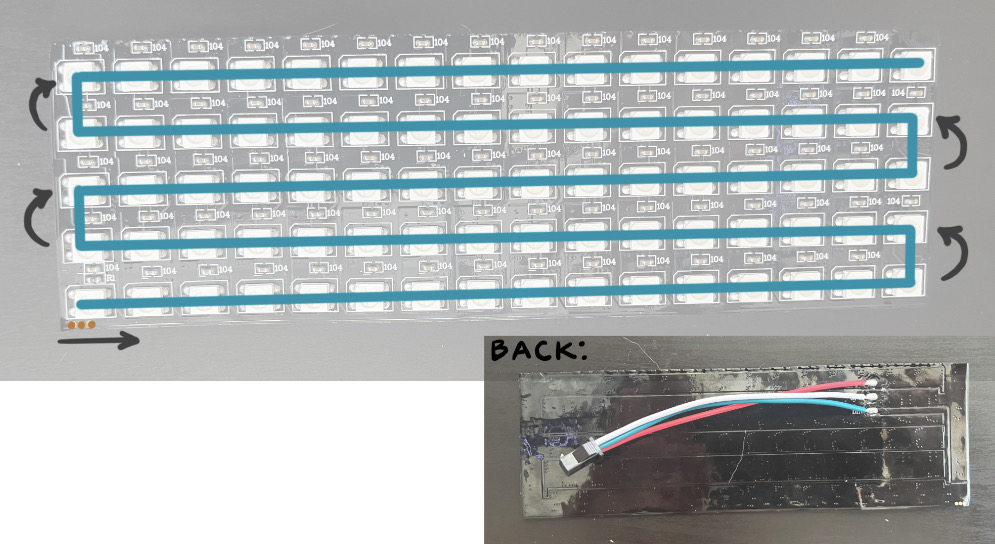
Top subgrid
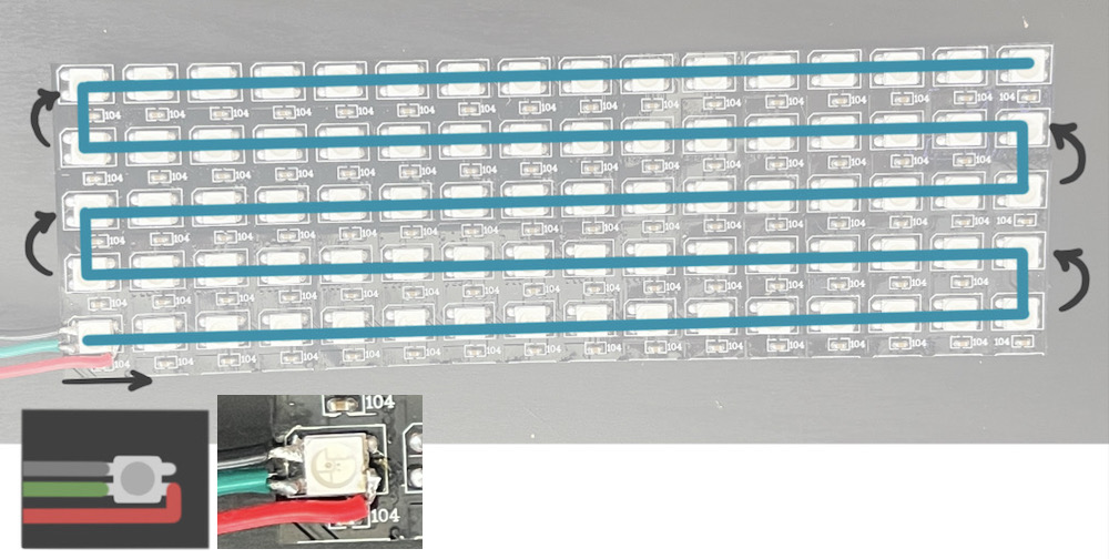
Middle subgrid
Bottom subgrid
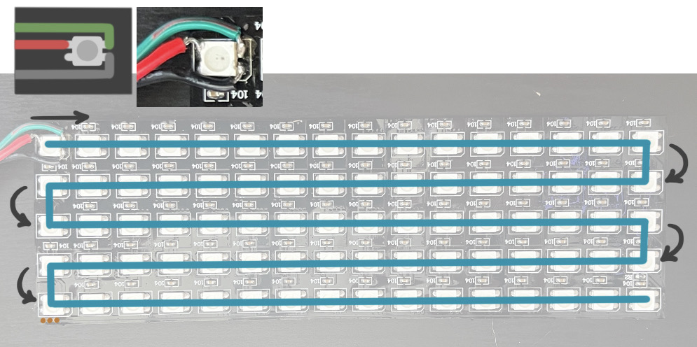
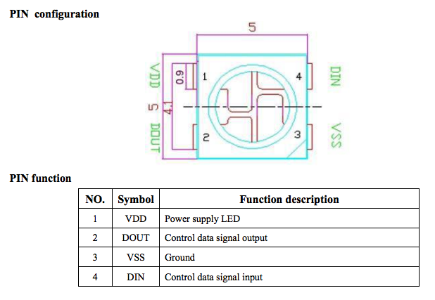
For the middle and bottom subgrids, I soldered my own connector directly onto the front of the starting pixel. Whenever I solder to the front of a neopixel I reference the diagram below. (screenshot from this WS2812B datasheet which is the datasheet for this product: adafruit bare WS2812B LEDs)
I rotated the subgrids so that the LED data arrangement always starts on either the bottom left or top left. But having two different possible start pixels makes the code a bit tricky!
Accommodating different start pixels in code
The top and middle subgrids start on the bottom left, and the bottom subgrid starts on the top left. If I tried to display the clock on both arrangements, one would be upside down. So the code needs to account for the two different directions of data travel.
I wrote a class LEDGrid to reference the LEDs conveniently with the syntax leds(x, y) = color. I defined two constants on the class BOTTOM_LEFT and TOP_LEFT (which are just numbers 0 and 1). When the LEDGrid instance is initialized, three variables are passesd in: WIDTH, HEIGHT, and start pixel (BOTTOM_LEFT or TOP_LEFT)
#define START_PIXEL LEDGrid::BOTTOM_LEFT  // or LEDGrid::TOP_LEFT

LEDGrid leds(WIDTH, HEIGHT, START_PIXEL);
The function xyCoordsToIndex accounts for the two start pixel layouts. The function converts the given x, y coordinates to an index on the one-dimensional line of data that snakes back and forth on the grid.
int xyCoordsToIndex(int x, int y) {
  // convert x, y coordinates to an index on the one-dimensional array
  // that snakes back and forth on the grid
  switch (_startPixel) {
    case BOTTOM_LEFT:
      if (y % 2 == 0) {
        return y * _width + x;
      } else {
        return y * _width + (_width - x - 1);
      }
    case TOP_LEFT:
      if (y % 2 == 0) {
        return (_height - y - 1) * _width + x;
      } else {
        return (_height - y - 1) * _width + (_width - x - 1);
      }
  }
}
See full code for LEDGrid.h class
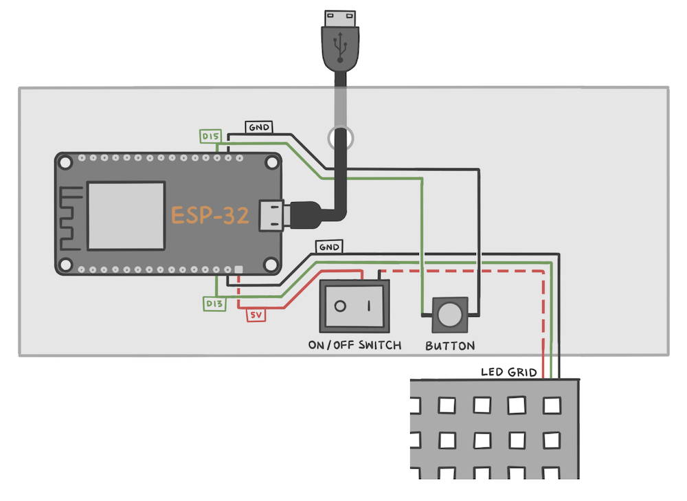
Wiring
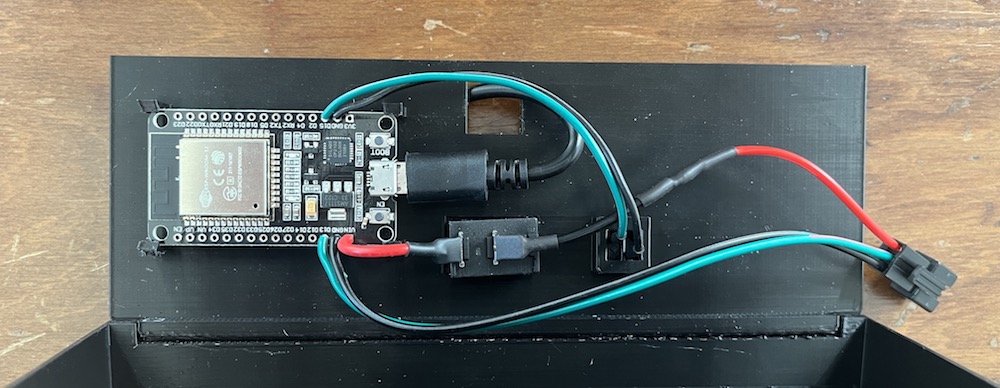
Schematic
Learn to program LEDs guide
The Rainbow Clock was designed to facilitate learning LED programming. This small 5x16 grid is meant to be a two-dimensional playground where someone can start learning the basics of LED programming without having to learn to solder or wire anything.
The Rainbow Clock Guide walks you through setting up your computer to upload code to the Rainbow Clock, and then coding your own LED patterns to display on the clock.
Write your own LED code
- Setup environment In order to upload your own LED code to the Rainbow Clock, you’ll need to install some software. This page will walk you through installing the Arduino IDE, adding the ESP32 board within the Arduino IDE, installing FastLED and ESP32Time libraries, and finally testing uploading code to the Rainbow Clock.
- Code simple LED grid patterns
This page will walk you through how to code some basic LED patterns, starting with turning on a single LED. Each pattern adds a layer of complexity onto the last, while calling out essential utility functions like
map()anddelay(). - How to re-upload the original clock code If you’ve uploaded your own code to the Rainbow Clock and you want to go back to its original function as a clock, this page will walk you through how to upload the original clock code.
Code
To jump right into the code, here’s the Github repository
As part of the introductory LED programming guide, I wrote a complete code breakdown, which explains the code that runs and displays a clock on the Rainbow Clock, grouped by functionality:
Clock code breakdown
- Basic code structure: Explains the basic setup and loop structure used for Arduino programming.
- How the LED code works (FastLED): Explains how the LED data structure is defined, and how to set the rainbow colors to the LED pixels.
- How the button code works: Explains how the state of the button is read, and how to detect a click and a long press.
- How the clock code works (RTC): Explains how the ESP32’s built-in RTC (Real Time Clock) module is used to keeps accurate time.
- How the EEPROM code works: Explains how the clock stores the last time on the EEPROM.
Thanks for reading!