Tree of Light Prototype
April 2022
What’s it for?
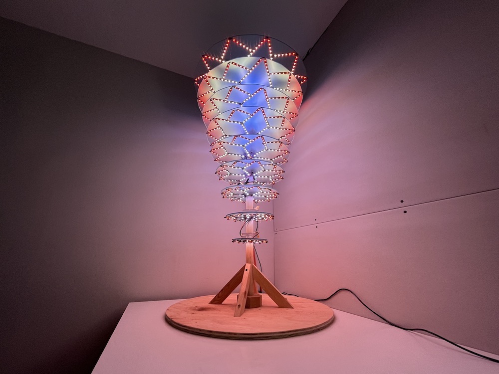
This 4-foot tall structure is a prototype for a larger LED structure we’re building this year that we’re calling the “Tree of Light” (that name is just a placeholder until we come up with a better one….) The actual final structure will be somewhere around 35-40 ft tall, but since it will take time to build, we decided to build a smaller prototype, so that I can start writing code and figuring out the algorithms for the light patterns. We made it out of plexiglass and wood. This post is about my process of adding LEDs to it!

Parts
- LED strips! WS2812B 60 LEDs/meter
- 5V 300A Power Supply
- ESP32-WROVER Board
- ESP32 Terminal Block
- 22 gauge wire. I had this leftover from a past project, and I lost the link!
- 3 pin wire connectors
First measure all the things
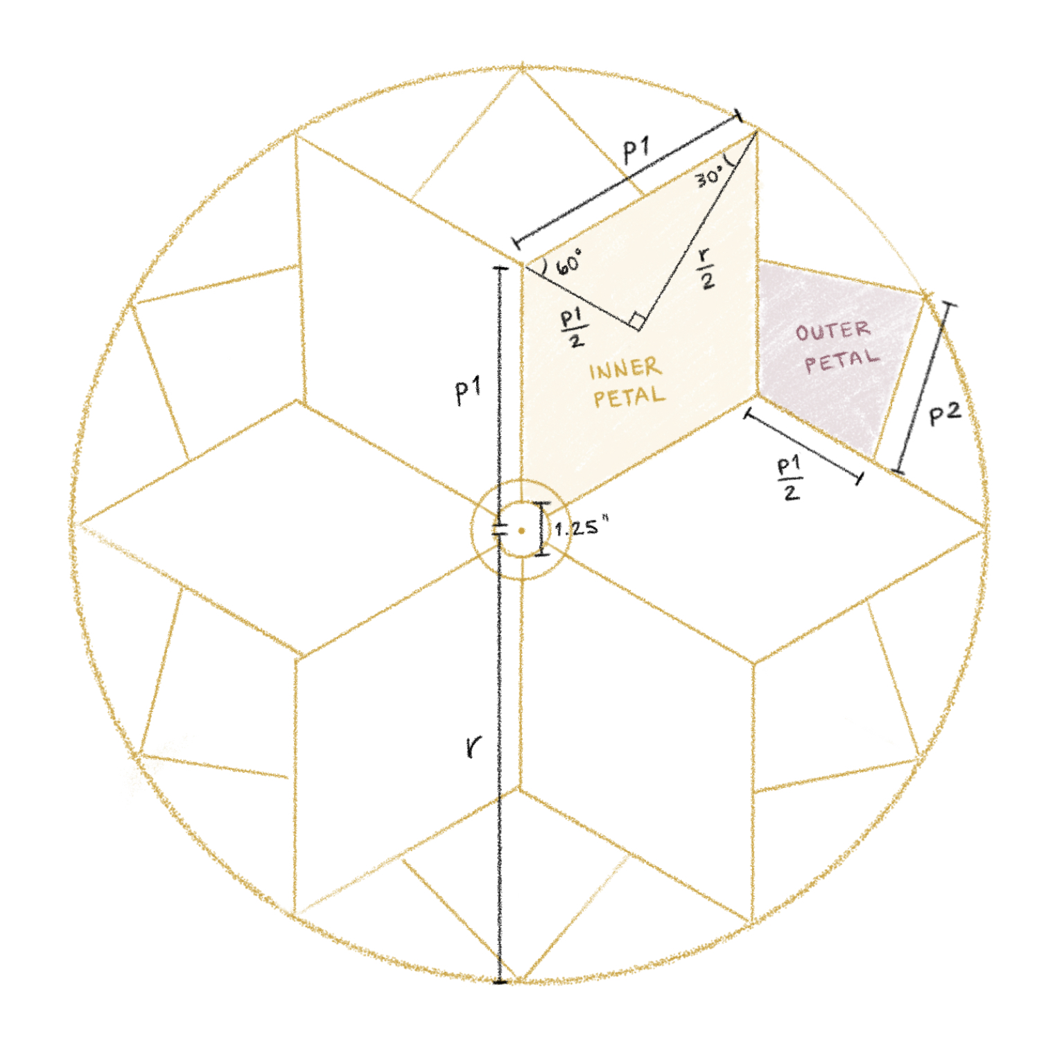
We want the LEDs to be arranged in this flowery shape on each disc. The first step is to gather some measurements based on the radius of each disc. There are two important lengths here which I’m calling p1 (length of the “inner petal” edge) and p2 (length of the “outer petal” edge)
| Variables | Equation | |
|---|---|---|
r |
radius of the disc | |
p1 |
length of edge of inner petal | r / 2 / sin(60°) * |
p2 |
length of edge of outer petal | 0.65 * p1 ** |
* I won’t pretend I figured this out without looking it up… thank you stackexchange
** I figured out this 0.65 in a silly way. Instead of working out the geometry, I coded the above diagram with JavaScript in an HTML canvas, and logged out ratio of p2 relative to p1
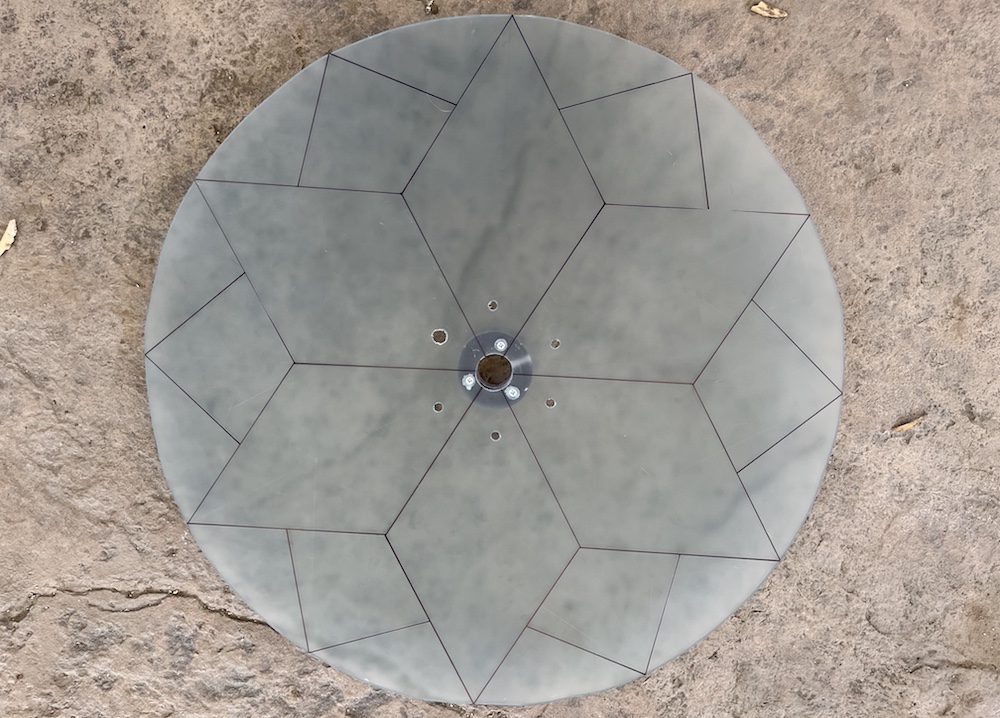
With all these measurements, I drew the pattern onto each disc, and cut pieces of LED strip to fit along these lines. As I did that, I recorded the number of LEDs in p1 and p2 for each disc in a spreadsheet, and when I was done I had cut a total of 1284 LEDs.
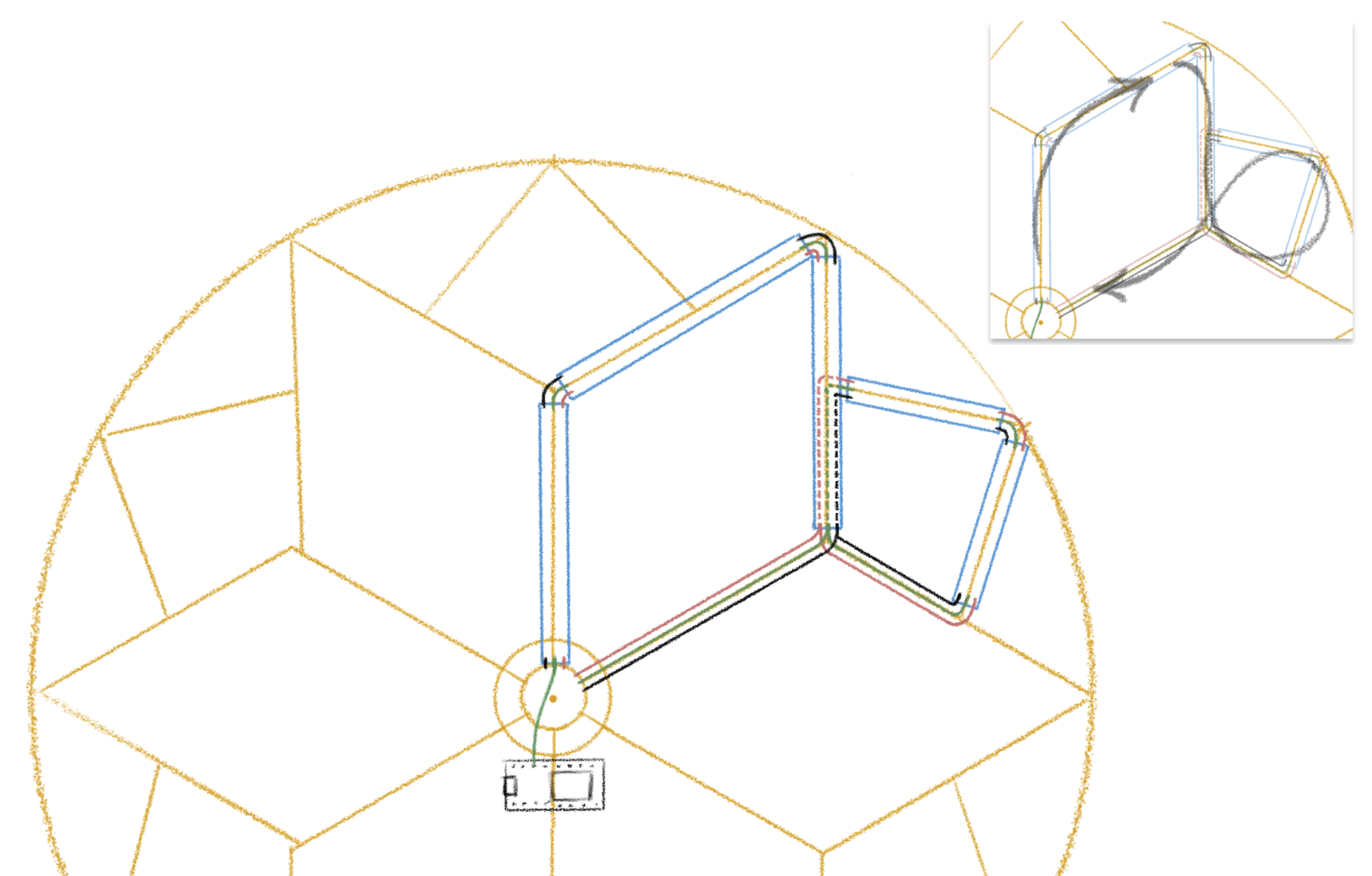
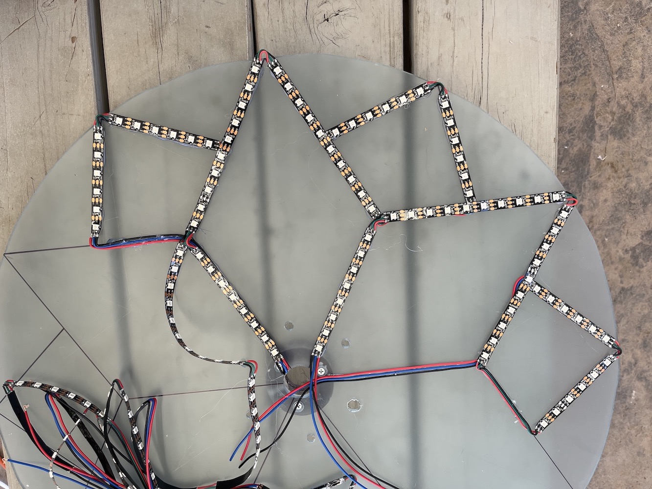
How to route the LEDs along these “petals”
I needed to figure out how to send the wires from the ESP32 board and how to route all the segments of LED strip around each petal. The ESP32 board (which will live at the top center of the model) has 19 output pins. My goals here were to stay within ≤19 pins, minimize the amount of wire used, and also hide the wires to keep it nice-looking.
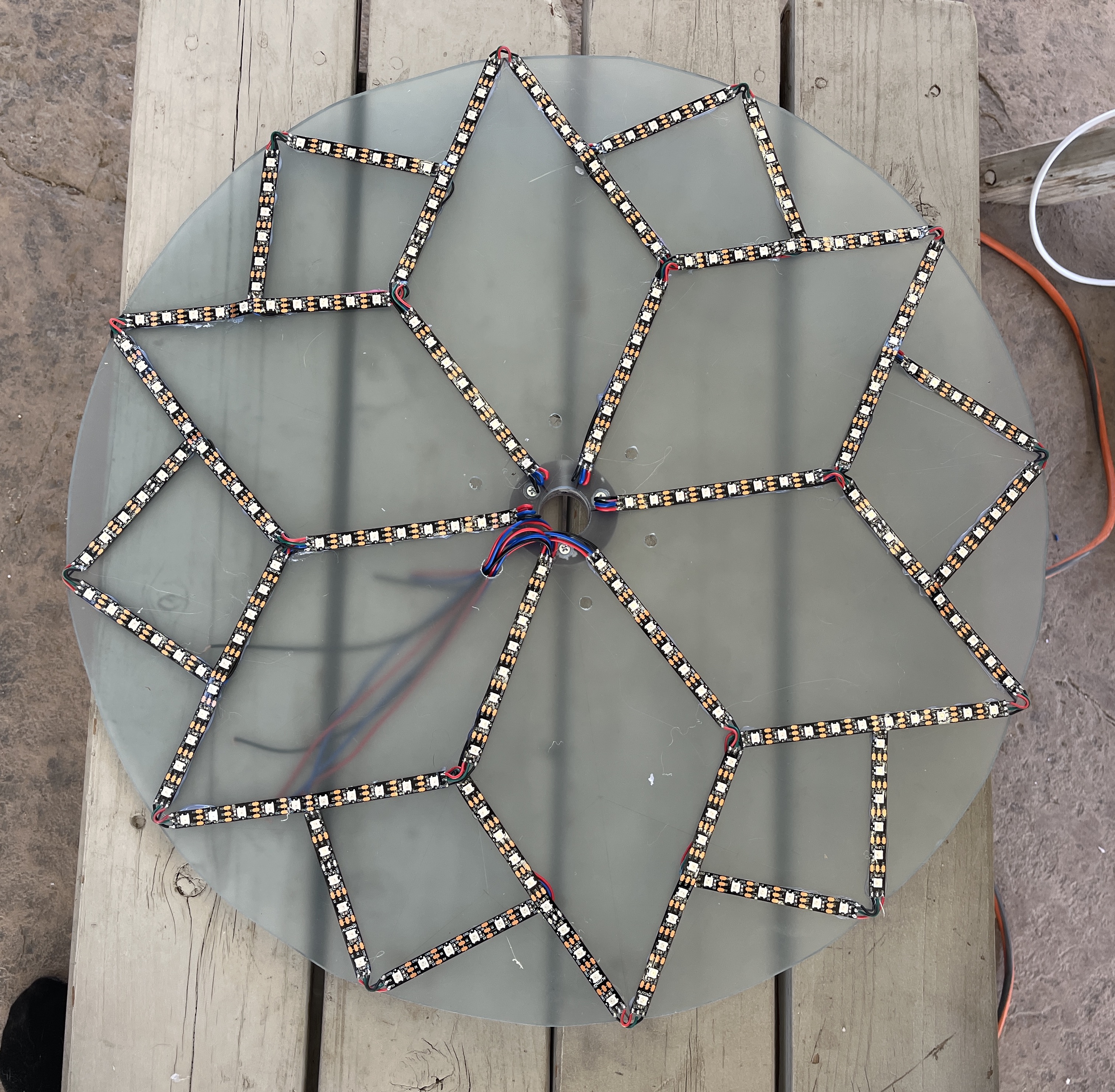
Here’s what that strip looks like all spread out:
Starting at the center of the disc, the LED strip will trace one inner and one outer petal, and then the pattern will repeat starting with the next inner petal. At first I planned to bend the LED strips on the 120 and 90 degree turns, but the LED strip felt too fragile, and wouldn’t sit flat enough. So I soldered short little jumper wires between each straight segment. I really enjoy soldering, so I didn’t mind the extra soldering time. :)
How big does the power supply need to be?
I happened to have this 5V power supply lying around. Here’s how I calculated whether it would be big enough, using P = V * A.
Watts P |
Volts V |
Amps A |
||
|---|---|---|---|---|
| Power Supply | 300W | 5V | 60A | |
| 1 meter LEDs (60 LEDs/m) | 12W | 5V | 2.4A | |
| per LED | 0.2W | 5V | 0.04A | |
| all LEDs (1284 LEDs) | 256.8W x 10%* = 282.48W |
5V | 51.36A 56.5A |
* This YouTube video recommended getting a power supply that has a capacity at least 10% higher than the max needed.
Where to inject power?
1284 LEDs is obviously too many LEDs to string together in one strand. To figure out how often I would need to inject power, I unrolled one of the LED strips I bought and set the whole thing to white on full brightness. It looked obviously yellow around 2/3rds of the way down the strip, after ~200 LEDs. So I injected power every 200 LEDs.
Dividing LEDs into groups
The power supply and ESP32 live on the top of the tree. I ran wires from there down through little holes we drilled in the plexiglass to the beginning of each LED group, and connected to the strips with 3-pin connectors. The LED groups that start on one disc and end on the next disc are also connected together with the 3-pin connectors.
Soldering and Glueing
The soldering and glueing went smoothly for the most part! The trickiest part was that I had to glue the LED strips on in a specific order, to make sure that the wires got glued down underneath the LED strips.
Code!
Setting each disc to a different color involved figuring out how to map LEDs from pins to discs. I ended up making one big long array of the LEDs for each disc chained together. Then I created a simple struct for each disc that stored a pointer to that disc’s LEDs, so I can access them per-disc.
Defining the FastLED array. Just a big list of all LEDs chained together:
CRGB *leds;

void setup() {

  leds = new CRGB[NUM_LEDS_TOTAL];

  uint16_t startIndex = 0;
  FastLED.addLeds<NEOPIXEL, PIN_1>(leds, startIndex, NUM_LEDS_PIN_1);
  startIndex += NUM_LEDS_PIN_1;
  FastLED.addLeds<NEOPIXEL, PIN_2>(leds, startIndex, NUM_LEDS_PIN_2);
  startIndex += NUM_LEDS_PIN_2;
  FastLED.addLeds<NEOPIXEL, PIN_3>(leds, startIndex, NUM_LEDS_PIN_3);
  startIndex += NUM_LEDS_PIN_3;
  FastLED.addLeds<NEOPIXEL, PIN_4>(leds, startIndex, NUM_LEDS_PIN_4);
  startIndex += NUM_LEDS_PIN_4;
  FastLED.addLeds<NEOPIXEL, PIN_5>(leds, startIndex, NUM_LEDS_PIN_5);
  startIndex += NUM_LEDS_PIN_5;
  FastLED.addLeds<NEOPIXEL, PIN_6>(leds, startIndex, NUM_LEDS_PIN_6);
  startIndex += NUM_LEDS_PIN_6;
  FastLED.addLeds<NEOPIXEL, PIN_7>(leds, startIndex, NUM_LEDS_PIN_7);

  // ...
}
Defining a simple data structure for the disc info:
struct Disc {
  uint8_t discIndex;
  uint8_t numLEDs; // number of LEDs in this disc
  uint16_t offset; // number of LEDs in tree before this disc
  CRGB *leds; // the LEDs for this disc
};
Creating the instances of each Disc, while accumulating an offset to track the disc’s position in the whole tree: This forum thread helped me figure out this nice simple way to keep a pointer for each disc’s LEDs (the &leds[offset] part below).
void setup() {
  // ...

  uint16_t offset = 0;
  for (uint8_t d = 0; d < NUM_DISCS; d++) {
    Disc disc = {d, NUM_LEDS_DISC[d], offset, &leds[offset]};
    discs[d] = disc;
    offset += disc.numLEDs;
  }
}
And then I can just set each disc to a different color of the rainbow!
void loop() {
  for (uint8_t d = 0; d < NUM_DISCS; d++) {
    for (uint8_t p = 0; p < discs[d].numLEDs; p++) {
      discs[d].leds[p] = rainbow[d];
    }
  }
  FastLED.show();
}
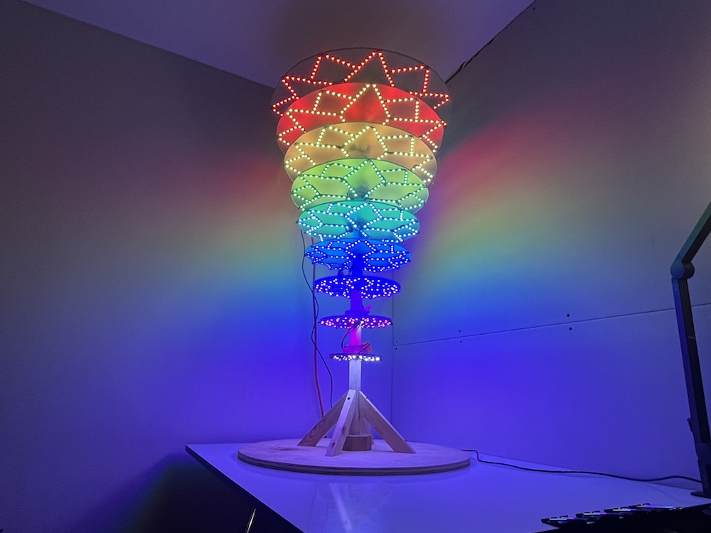
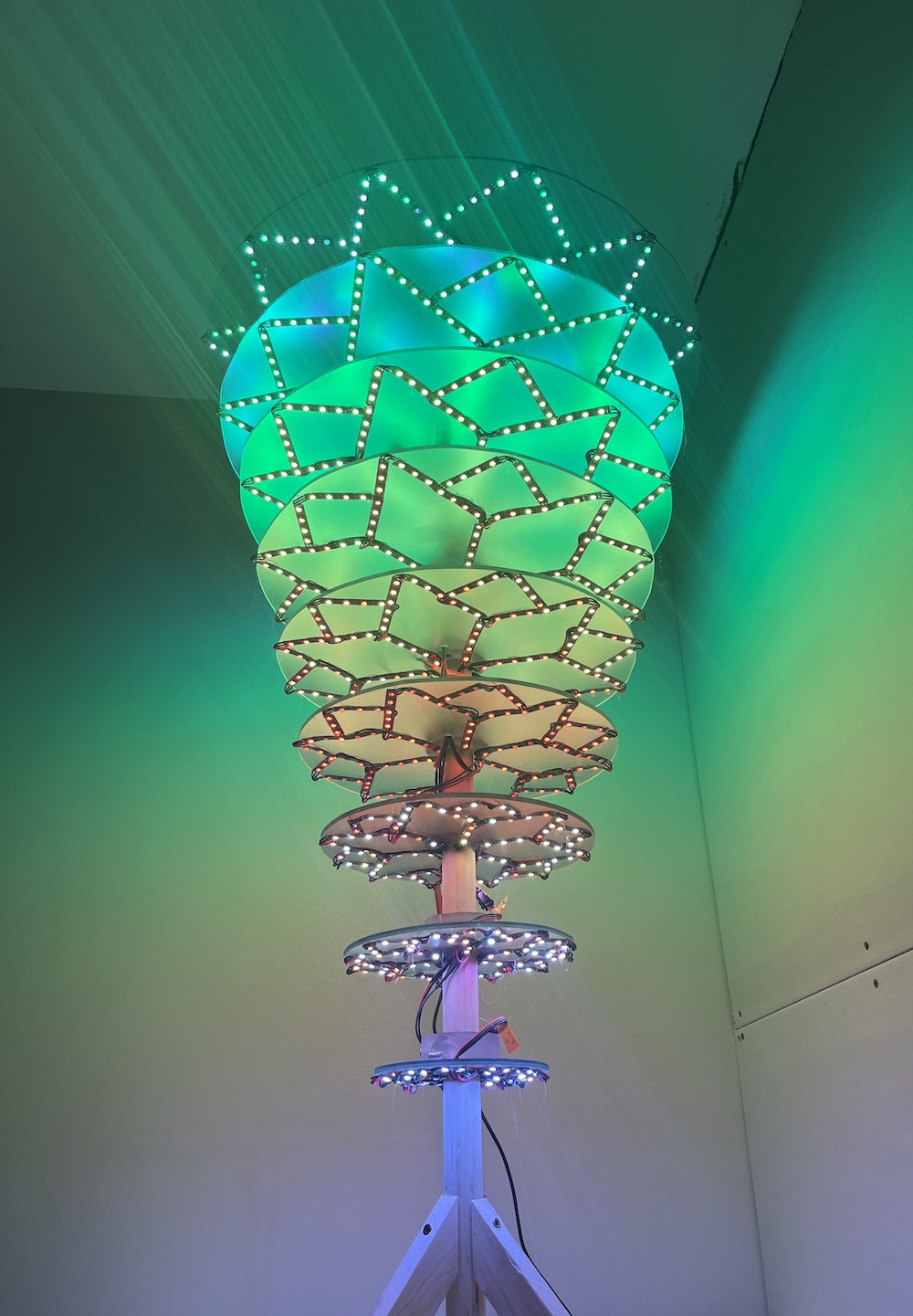
Okay but does it do anything yet??
This post is meant to be about the build, not the light patterns. I will be developing a lot more light patterns for this thing! But if you read this far down this post, then I love you. And you probably want to see this thing do something cool! So here’s a nice simple one.
-Micky